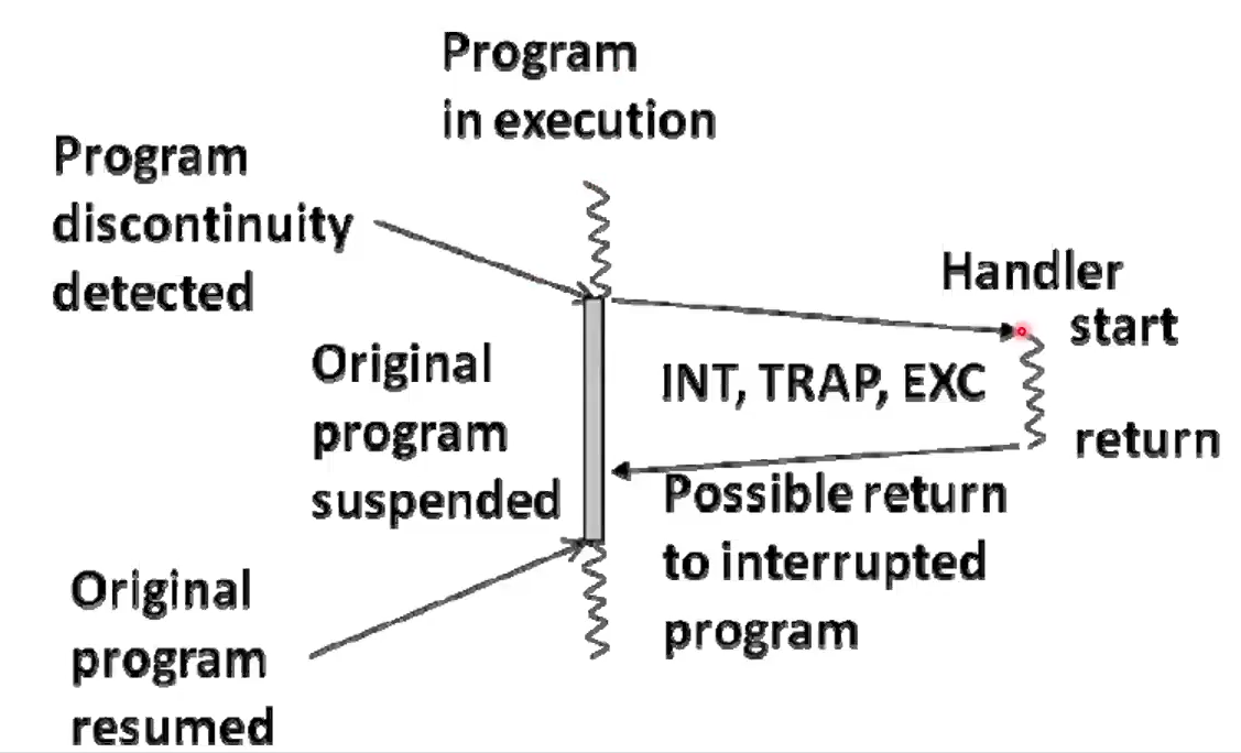
When a discontinuity occurs, it must be handled. This is managed at the Microarchitecture level
Synchronicity
Synchronous
Synchronous events occur at well defined points aligned with activity of the system, e.g. opening a file. They are usually invoked by a program.
Asynchronous
Asychronous events occur unexpectedly with resspect to ongoing actvity on the system, e.g. a user pressed akey on a keyboard. They are external to the activity of a program.
Classifications
Interrupt
Asynchronous events usually produced by I/O devices which must be handled by the processor by interrupting execution of the currently running process
Trap
Synchronous events producted by special instructions typically used to allow secure entry into Operating System level code, e.g. a system call to open a file.
Exception
Synchronous evetns usually associated with software requesting something the ahrdware can’t perform, e.g. illegal addressing, illegal Opcode, dividing by zero, etc.
Handler
- $k0 = PC
- Assert interrupt acknowledgement
- PC = mem[IVT]
- user mode ? USP =
sp = SSP, mode = kernel - push previous mode on stack
- disable interrupts (DI)
HANDLER:
- (Handler starts with interrupts disabled)
- push $k0 onto kernel stack
- enable interrupts (EI)
- save processor registers to kernel stack
- execute device Subroutine, e.g. mouse interrupt
- restore processor registers from kernel stack
- disable interrupts
- pop $k0 from kernel stack
- return to original program using RETI
RETI:
- PC = $k0
- mode = pop mode from kernel stack
- user mode ? SSP =
sp = USP - enable interrupts
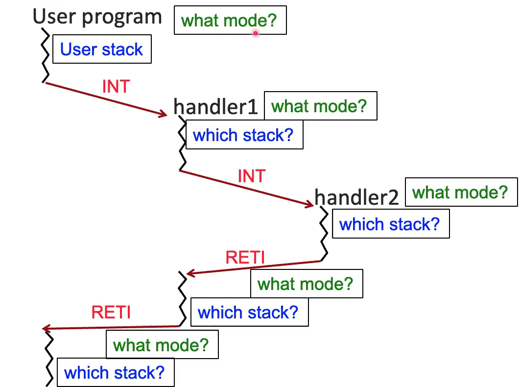
Cascading handler calls
- This is essentially just an elevated function call. Accordingly, you can interrupt an interrupt just like you can call a function within a function. However, we don’t use the user stack like a normal function. Instead we use a kernel (system) stack that is managed by the Operating System. This means we have to have two additional registers for a system stack pointer, and a user stack pointer.
- There is no way to prevent an interrupt from happening before $k0 happens, which is a problem. We would need groups of machine instructions to behave atomically, i.e. as if they were all executed as a single instruction, in order to fix this issue. Therefore, we introduce another register to store whether or not interrupts are enabled, and disable this register when we are saving or restoring our processor registers within a given handler. We therefore disable interrupts in our interrupt macrostate. This neccesitates that there is a way to enable and disable interrupts. In LC 2200, there are two instructions for this.
- Also need to atomically enable interrupts and set the PC to return from the handler
- We also have to keep track of user/kernel mode. Only kernel mode can run RETI or touch the kernel stack.
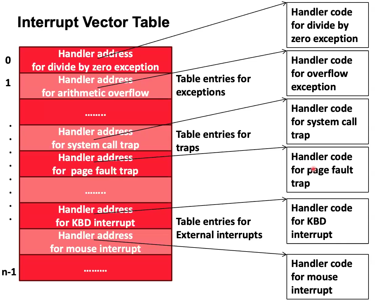
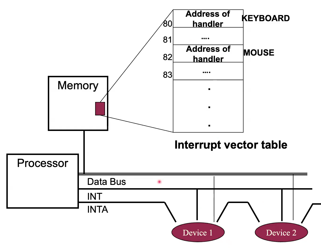
Interrupt Vector Table
Map from interrupt ID to address of handler code in Memory.
This allows the Microcode to begin the execution of a handler by grabbing the interrupt ID, e.g. from the Exception / Trap Register (ETR) on LC 2200.
LC 2200
Exception / Trap Register (ETR)
Contains a unique ID stashed by the hardware to indicate the type of discontinuity
Interrupt Enable Register (IER)
1 when interrupts are enabled, and vice versa.
Interrupt Enable (IE)
Set IER
Disable Interrupt (DI)
Clear IER
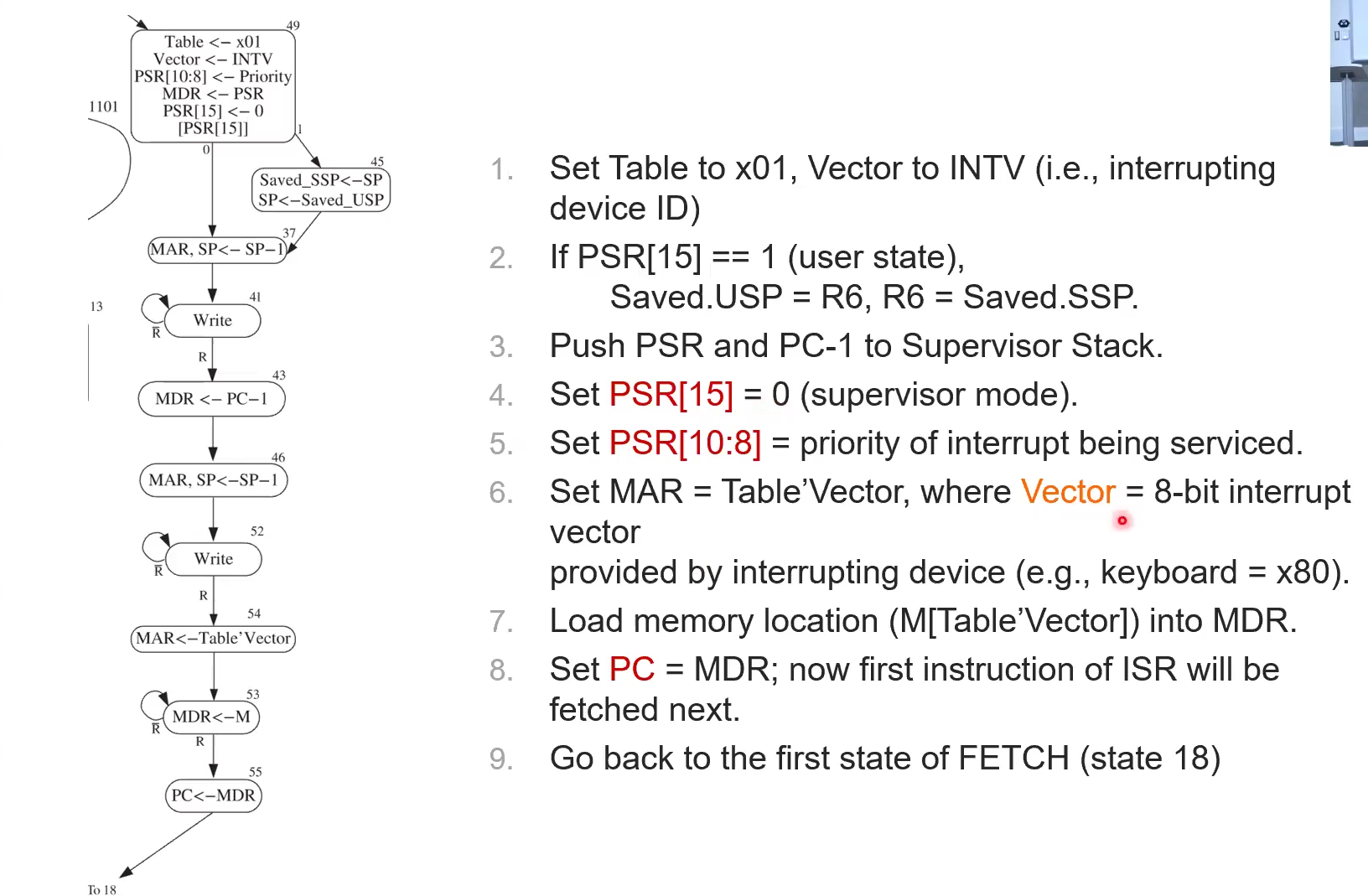
INT Macrostate
Take an interrupt after execute macrostate, before fetch. If interrupt flag (INT) is set and IE = 1, then take it.
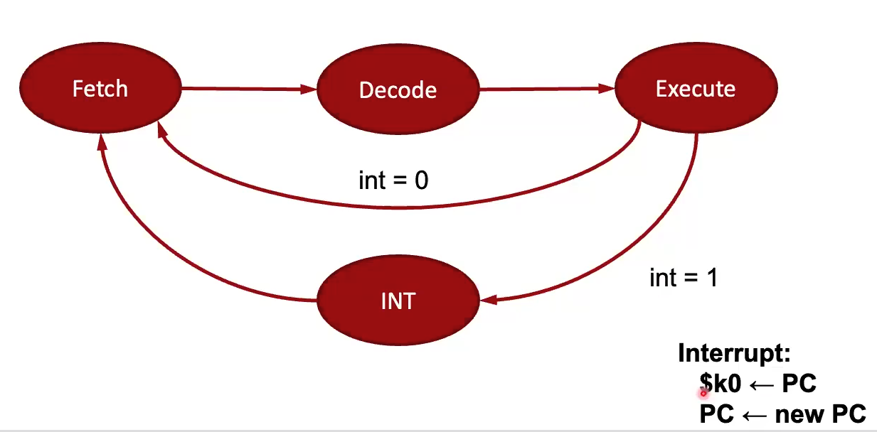
 If the interrupt get taken, it basically does a [[LC 2200#Instructions#jalr]]
There is an INT line that will be set to 1 if any one of the connected devices need to interrupt.
This INT 1 or 0 value will be used to decide whether or not to take the INT macrostate.
If IE is off ignore INT
Upon entering INT macrostate, INTA is raised by the Microcode
If a device isn’t interrupting, it passes through the INT signal, else it asserts its device ID onto the Data bus, so that the Control Unit can save it to the ETR. Then that value in the ETR is used as an index into the IVT so that the PC can be set to the beginning of the interrupt Subroutine.
If the interrupt get taken, it basically does a [[LC 2200#Instructions#jalr]]
There is an INT line that will be set to 1 if any one of the connected devices need to interrupt.
This INT 1 or 0 value will be used to decide whether or not to take the INT macrostate.
If IE is off ignore INT
Upon entering INT macrostate, INTA is raised by the Microcode
If a device isn’t interrupting, it passes through the INT signal, else it asserts its device ID onto the Data bus, so that the Control Unit can save it to the ETR. Then that value in the ETR is used as an index into the IVT so that the PC can be set to the beginning of the interrupt Subroutine.
RETI
return from exception/trap/interrupt atomically enables interrupts and sets the PC to return from the handler
- PC = $k0
- mode = pop mode from kernel stack
- user mode ? SSP =
sp = USP - enable interrupts
LC3
Handled by
- Save CPU state (Processor Status Register - PSR)
- Last 3 bits of PSR are NZP
- Raise CPU priviledge level
- Call Operating System routine
- Restore CPU State
- Restore Priviledge level
- Resume execution
Interrupts
- An I/O device is reporting a completion or an error
- An unscripted Subroutine call, triggered by an external event
- Supervisor stack, unique call stack for interrupts, different from user stack
- Every Fetch, LC3 polls for an interrupt
- Modifications to the hardware of the datapath and I/O, and additional software to allow an external device to cause the CPU to stop current execution of the original program
- Can be signficantly more efficient than polling
- Useful in an environment where there are numerous devices and concurrent activities
- Polling is better when there is a high likelihood of the CPU having nothing better to do
- The RTI is a priviliedged instruction that undoes what an interrupt or trap does, i.e. what the microcode does for an interrupt service routine or trap
- Can only be executed in supervisor mode
TRAPs
- A program-initiated interrupt
- The program is calling a priviledged Operating System subroutine, e.g. Read a line from a file
- Call trap with a argument that specifies which operation it should execute
Trap Vector Table
| Vector | Symbol | Routine |
|---|---|---|
| x20 | GETC | read a single character (no echo) |
| x21 | OUT | output a character to the monitor |
| x22 | PUTS | write a string to the console |
| x23 | IN | print prompt to console, read and echo character from keyboard |
| x25 | HALT | halt the program |
Exceptions
- Something unanticipated has happened
- Hardware error in the CPU or memory
- Program error (illegal opcode, division by zero)
Memory Mapped I/O
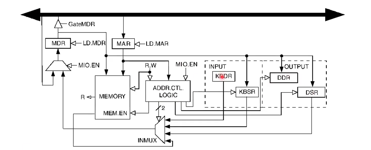
Keyboard
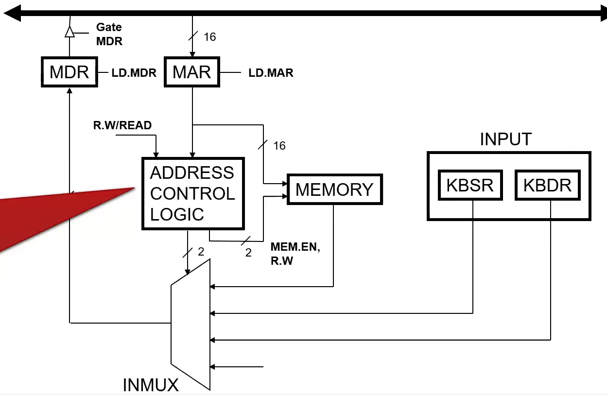
KBSR
xFE00 Keyboard status register
- Only uses 1 bit
- Bit 15 is set when a character is available
KBDR
xFE02 Keyboard display register
- Only uses 8 bits
- Read only
- Reading clears KBSR
Read Characters from Keyboard
.orig x3000
ld r4, term
lea r2, buffer ; init buffer pointer
start ldi r1, kbsrA; see if char is there
	BRzp start ; "are we there yet" until character is present
	ldi r0, kbdrA ; get the character typed
	str r0, r2, 0 ; store it in buffer
	; terminate if they typed ctrl-z
		not r0, r0
		add r0, r0, 1
		add r0, r0, r4
		BRz quit
	add r2, r2, 1 ; inc buffer pointer
	BR start ; do it again
quit halt

term .fill x001A ; ctrl-z
kbsrA .fill xfe00
kbdrB .fill xfe02
buffer .blkw x0100
.end
Display
DSR
xFE04 Display status register
- Transferring a character to DDR clears DSR
- When monitor is finished processing a character it sets DSR bit 15
- “Please sir, may I have another?”
DDR
xFE06 Display display register
- Transfer character to this address to print it on the monitor
Write string to display
.orig x3000
lea r2, buffer ; init buffer pointer

start ldr r0, r2, 0 ; r0 <- char
	brZ quit ; terminate on null
wait ldi r3, dsrA ; are we ready?
	brZP wait
	sti r0, ddrA ; send R0 to monitor
	add r2, r2, 1 ; inc buffer pointer
	br start ; loop

quit halt
dsrA .fill xfe04
ddrA .fill xfe06
buffer .stringz "Hello, World!"
.end